Transparent plastic cover injection mold is a single cavity mold with multiple parting surfaces among the types of injection mold structure. The mold adopts the standard mold frame with fine spout, which is commonly known as “three-platen mold” structure, in order to realize the fully automatic sequential mold parting process. The casting system condensate and product parts are taken out on different parting surfaces.
- Structure and working process of the mold
Structure of the mold. The structure assembly diagram of the transparent plastic cover shell injection mold is shown in Fig. 4.85. (1)
(2) The working process of the mold. After the mold is closed and mounted on the horizontal injection machine, under the action of a certain injection pressure, the plastic melt is injected uniformly into the cavity of the mold along the pouring system through the nozzle, and the gas in the cavity is discharged from the exhaust groove opened on the pusher plate 9 to complete the injection process. Under the action of the circulating cooling system, the melt is cooled and molded in the cavity. The molded product shrinks on the dynamic mold core insert 19.
Figure 4.85 Transparent Plastic Shell Injection Mold Structure Assembly Diagram
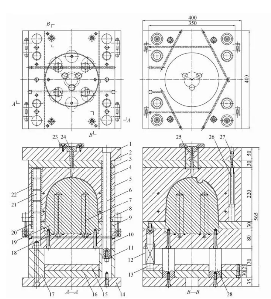
1-Fixed mold plate; 2, 4, 20, 22-guide sleeve; 3-exit channel plate; 5-fixed mold plate; 6, 21-guide pillar; 7-waterproof piece; 8-pull hook; 9-push plate; 10-movement mold plate; 11-limit retaining ring; 12-reset spring; 13-reset rod; 14-movement mold plate; 15-pusher rod fixing plate; 16-pusher rod plate; 17-support block; 18-seal; 19-movement mold core insert; 23-positioning ring; 24-gate sleeve; 25-pull rod; 26-pull rod; 28-supporting rod; 27-limit screw; 28-supporting rod; 19-movement mold core insert: 23-positioning ring; 24-gate sleeve; 25-pull rod; 26-pull rod; 28-supporting rod; 28-supporting rod; 27-limit screw; 28-pulling rod; 28-pull rod Mold core insert:23-locating ring:24-gate sleeve:25-pull rod;26-pull rod;27-limit screw;28-supporting post
As shown in Fig. 4.86, it is the state diagram of the mold after opening and pushing out the parts. When the mold is opened, the fixed mold seat plate 1 is fixed on the fixed mold connecting plate of the injection machine without moving, and when the movable mold moves backward, the fixed plate 5 is driven by the pulling hook 8, while the manifold pulling rod 25 fixed on the fixed mold seat plate pulls the sprue condensate, so that the mold is separated from the parting surface I, and the sprue condensate is automatically detached from the molded part. The moving mold continues to move backward, under the action of the pull rod 26 and limit screw 27, the sprue plate 3 and the fixed mold base plate separate from the parting surface I, so that the sprue condensate is automatically dislodged from the manifold pull rod and the sprue sleeve 24, and completes the process of automatic separation of the sprue condensate. The moving mold continues to move backward, pulling off the pulling hook, so that the mold is separated from the parting surface Ⅲ, and the molded parts are left on the core insert of the moving mold due to molding contraction.
Fig. 4.86 The state of the mold after opening and pushing out the parts.
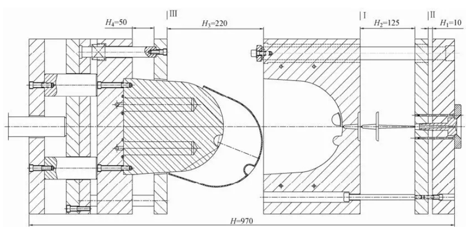
Finally, the hydraulic system of the injection machine drives the ejector rod to push the pusher pad 16 and the pusher fixing plate 15 of the mold, and the reset lever 13 fixed between the pusher pad and the pusher fixing plate pushes the pusher plate 9 fixed thereto with screws to push the molded part out of the moving mold core insert.
The closing height of the mold is H0 = 565 mm; the closing height of the mold is the height of the mold between the fixed mold base plate and the moving mold base plate after the mold is closed.
The distance of separation at parting surface I is H2=125mm, the determination of H2 must satisfy the following conditions: H2 = the length of the sprue + (5~10) mm; H2 = the length of the sprue + (5~10) mm; H2 = the length of the sprue + (5~10) mm.
The distance of separation at parting surface Ⅱ is H1=10mm, the purpose of which is to realize the automatic separation of the sprue and the drawbar.
The distance between the mold and the parting surface Ⅲ is H3=220mm to ensure that there is enough space for the parts to fall down automatically.
The distance that the mold pusher plate moves is H4=50mm, to ensure that the part is pushed away from the core insert of the moving mold.
The total height of the mold after opening is
H=HO+H1+H2+H3+H4=565+10+125+220+50=970mm, the total height of the mold after molding must be less than the maximum opening distance between the fixed plate of the moving and fixed molds on the injection machine, i.e., the maximum distance moved by the fixed plate of the moving mold of the injection machine.
- Structural characteristics and quality requirements of product parts
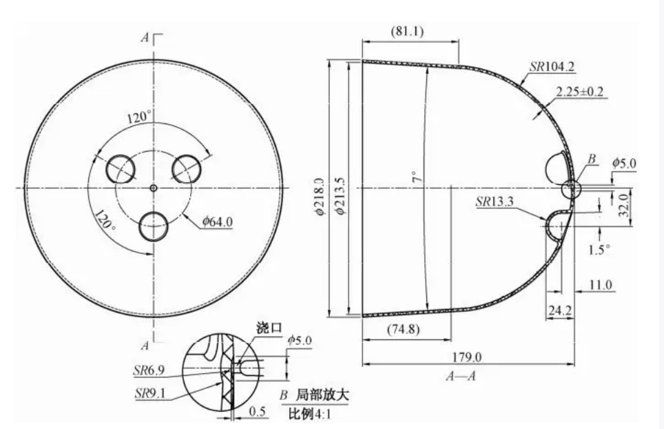
The structure of the product is shown in Fig. 4.87. The material is transparent styrene PS, which is characterized by good impact strength, good heat resistance, oil resistance, chemical resistance and high modulus of elasticity. Therefore, it is widely used to make industrial products that are oil, heat, and chemical resistant, as well as parts such as instrument panels, housings, junction boxes, and various switch buttons. The average shrinkage rate of the material is 0.4%. When the product is used as a shell, its dimensional accuracy requirements are low, but the surface appearance quality requirements are high. The surface of the parts is glossy, and the appearance requires no water lines, no scratches, no black spots, no flying edges and other defects. The maximum diameter of the bottom of the product is p218mm and the height is 179mm. there are three concave holes in the upper part of the product, which can be used to grasp the product with three fingers. Because the material is easy to produce cracks in the molding, so the mold release after molding needs to have a larger mold release slope, the product’s mold release slope is 3.5 ° on one side. According to the principles and requirements of the selection of parting surface, the parting surface can only be selected on the plane at the bottom of the product, and the mold county adopts the structure of 1 mold and 1 cavity. For this type of structure, the design of the mold structure should be based on the structural characteristics of the product and the process of injection molding to choose the appropriate location of the gate. In order to make the plastic melt can be evenly filled into the mold type, and the gas in the cavity will be discharged from the exhaust groove opened on the parting surface, it can not be fed from the bottom and the periphery with side gates, and can only choose the gate in the center of the top surface of the product, and feed the material from the top center of the product. In order to minimize the impact of the gate on the appearance, it was determined that the gate should be fed by the structure of a point gate.
Figure 4.87 Product Structure
- Mould pouring system
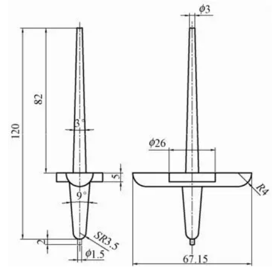
In order to guarantee the required quality of the product, a point-gate feed is selected when feeding the mold from the top of the product. Thus, the sprue system cannot be removed together with the product on the parting surface where the maximum contour of the product is located, but only separately on another parting surface, as described in the mold opening process. The dimensions of the point gate and the sprue system are shown in Figure 4.88.
Fig. 4.88 Dimensions of point gates and sprue systems
The characteristics and application of the counterpoint sprue can be found in the plastic injection molding of a transparent box lid.
The gate sleeve forming the main flow path is shown in assembly figure 4.85, part 24. The fit between the sprue sleeve and the release channel plate is particularly important because of the relative movement between them during mold opening and closing. If the fit gap is too large, the melt will overflow along the fit gap and make demolding difficult, while if the fit gap is too small, it will be obstructed during mold closing and will wear out quickly. Therefore, the end of the gate sleeve needs to be tapered to prevent the melt from the pouring system from entering the sliding mating surface when the mold is closed. In addition, it allows for a smooth opening and prevents wear on the sliding mating surfaces. The taper of the taper structure is approximately 6° to 10°. The form of assembly of the gate sleeve in the mold is shown in Fig. 4.89.
Four mold opening hooks are installed between the fixed and moving mold plates to achieve the parting sequence of the different parting surfaces of the mold. The structure of the hooks has been standardized as shown in Fig. 4.24.
Figure 4.89 Assembled Form of Potting Boot in Mold
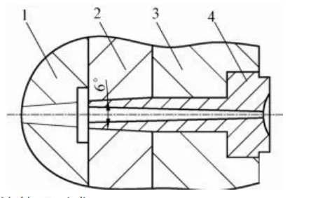
1-Fixed mold plate; 2-Despouring channel plate; 3-Fixed mold seat plate; 4-Gate sleeve
- Molding parts of the mold
(1) Cavity parts: molding the outer surface of the cavity, in order to ensure that the mold has sufficient strength, can be made with the template as a whole structure. But in order to obtain the cavity surface roughness of low requirements, must use high-quality steel in view of the economy of manufacturing costs, in the selection of standard mold frame, can be required to set the template using 718 or 738 material, in order to make the cavity in the molding to obtain a good appearance of the quality of the product. Fixed template parts diagram shown in Figure 4.90.
Figure 4.90 Part Diagram of Fixed Plate
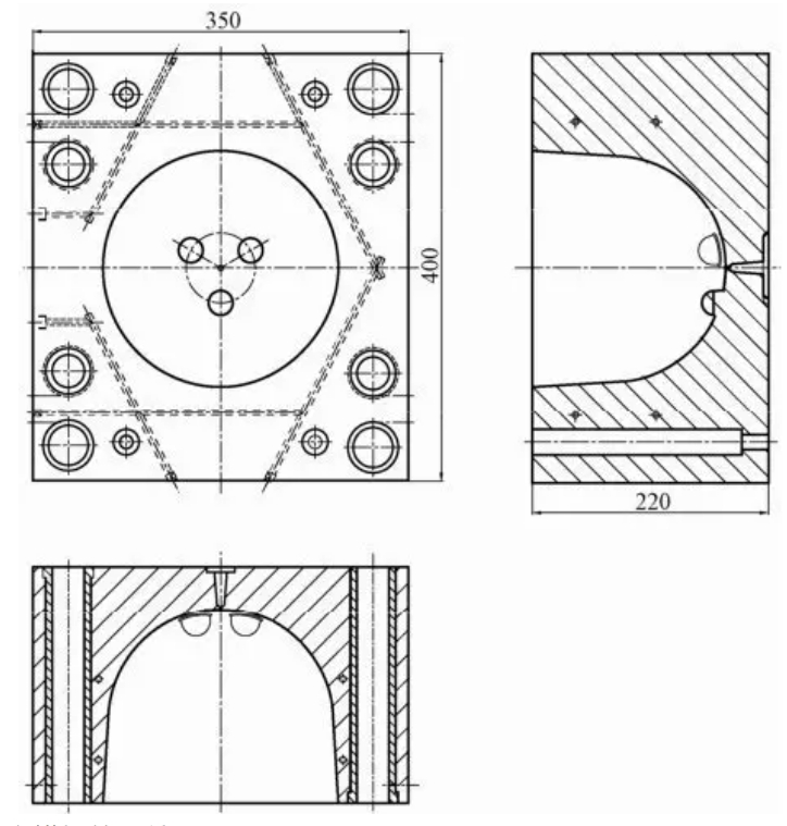
(2) core parts: molding the inner surface of the molded part of the dynamic model core, designed as a mosaic structure, with hexagonal screws fixed in the dynamic template. The structure of the core parts shown in Figure 4.91.
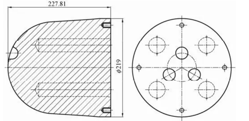
Figure 4.91 Structural diagram of core parts
In order to reduce the roughness of the mold cavity surface, the use of excellent polishing performance of imported mirror mold steel S136 material production, heat treatment and its hardness can reach 60 ~ 65HRC, polishing process can be obtained after the surface roughness of Ra0.4um, so that the surface of the molded parts to meet the requirements of the product finish.
- Mold selection of the standard mold frame structure
As can be seen from the assembly diagram of the transparent plastic shell injection mold structure shown in Figure 4.85, the mold uses a standard mold frame with a fine spout. Its model is 3540-DDI-A plate 220-B plate 80-440-0. The structure of the mold frame is shown in Fig. 4.92.
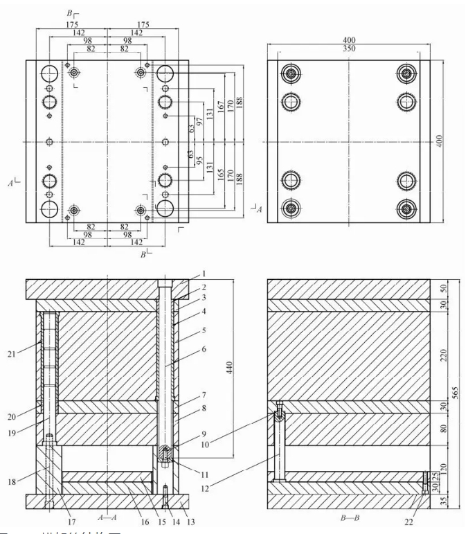
Figure 4.92 Structural Drawing of Mold Frame
1-Fixed mold base plate; 2, 4, 20, 21-guide sleeve; 3-exit channel plate; 5-fixed mold plate; 6, 19-guide pillar; 7-pusher plate; 8-dynamic mold plate; 9, 10, 14, 18, 22-hexagonal socket head cap screws; 10-limit retaining ring; 12-reset lever; 13-dynamic mold base plate; 15-pusher fixing plate; 16-pusher plate; 17-supporting English
In the standard mold frame model, 3540 means that the length of the standard mold frame on the parting surface is 400mm and the width is 350mm, DDI stands for the structure type of the mold frame, and the thickness of its A-plate is 220mm and that of its B-plate is 80mm, [440] means that the total length of the fixed mold support guide pillar in the mold frame is 410mm, and [O] means that the support guide pillars are installed in a way that they are close to the four corners of the mold plate, i.e., the guides installed between the fixed and movable mold plates are not installed. O” means that the supporting guide pillar is installed near the four corners of the template, i.e. the guide pillar installed between the fixed template and the moving template is close to the inside of the template, and the supporting guide pillar installed on the fixed template is located at the place where the template is outside.
The material of each plate of the mold frame is Q235, the material of the guide pillar, guide bush and reset lever is T8A, and the socket head cap screws and limit retaining ring are standard parts.
As can be seen from the structure of the mold frame shown in Fig. 4.92, the difference between the standard mold frame for fine spout and the standard mold frame for large spout is that the fixed mold part is different. The fixed mold of the standard mold frame for fine spout has an additional decanting plate between the fixed mold base plate and the fixed mold plate, and the weight of the fixed mold plate and decanting plate is supported by the additional four supporting guides when the mold is opened. The fixed formwork and the release plate are movable on the supporting guides. In the case of large spout standard mold frame, the fixed mold is fixed together with the fixed mold seat plate and fixed mold plate by using hexagonal screws, and the fixed mold plate is fixed together by using hexagonal screws.
- Mold temperature control system
Since the material used for the molded part is transparent polystyrene PS, which is a thermoplastic, it is necessary to cool the mold in the range of 20~60℃ during the molding process in order to shorten the molding cycle. For the temperature control system of the mold, a double-layer circulating cooling water channel is used in the cavity part of the mold to control the cooling. For the cooling channels, please refer to the part drawing of the fixed mold plate shown in Fig. 4.91. In the case of the dynamic core insert, a side-by-side spacer cooling system is used (see Fig. 4.93), in which the cooling holes are drilled in the core and a brass spacer is installed inside the holes to separate the holes into two halves, with only the top connecting to form a circuit. An “O” shaped rubber sealing ring must be installed on the face where the moving core insert is combined with the moving template to prevent cooling water from penetrating into the mold cavity and affecting the molding quality of the product.This type of circulating cooling not only makes the structure of the mold simple, but also allows for good cooling of molds with deeper cores.
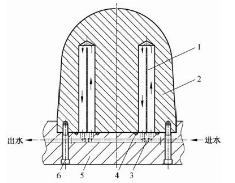
Fig. 4.93 Structural schematic diagram of circulating cooling of water barrier sheet
1-Watertight piece; 2-Dynamic model core; 3-Plug; 4-“O”-shaped sealing ring; 5-Dynamic template; 6-Hexagon socket head screws
The material of the waterproof piece is usually made of brass sheet, the main purpose is to prevent rust.
- Mold release mechanism
Because the product requires transparent characteristics, the mold release mechanism can not be used to avoid the top bar ejection, to avoid traces of the top bar ejection, affecting the aesthetic effect of the product. Therefore, a push plate is used to push out the mold release mechanism. Push plate with hexagonal screws fixed in the reset lever, and in the reset lever on the moving template and push rod between the fixed plate additional compression springs, so that after opening the mold push plate demolding mechanism can be automatically reset. The structural composition of the push plate release mechanism is shown in Figure 4.94.
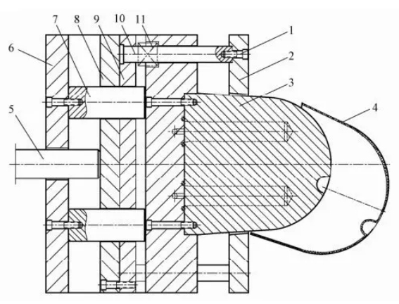
Figure 4.94 Structural components of the pusher push-out mechanism
1-hexagonal screws; 2-push plate; 3-move the model core; 4 a molded plastic parts: 5-injection machine on the top bar: 6-fixed mold seat plate; 7-support column: 8-push rod pads; 9-push rod fixed plate: 10-reset rod: 11-reset spring
(1) The structure of the push plate pushing mechanism. The structure of the push plate launching mechanism consists of the following parts: the top bar on the injection molding machine, push rod fixed plate, push rod pad, reset lever, reset spring, push plate and hexagon socket head cap screws. The principle of the mold launch can be seen in the working process of the mold chapter.
(2) The characteristics of the push plate launching mechanism. Push plate launching mechanism because of the role of large area, launching force is large and uniform, smooth movement, and by the entire periphery of the plastic parts of the end face of the molded plastic parts will be launched, so no traces of the launch of the plastic parts, especially suitable for transparent plastic parts and high precision requirements of the use of plastic parts. However, if the core and the pusher plate do not fit well, burrs will appear on the molded part, and the molded part may be retained on the pusher plate. In order to avoid the difficulty of matching the pusher plate with the core during processing, the pusher plate push-out mechanism is mainly used when the inner hole of the part is round or other simple shapes.
In order to make the push plate in the process of launching and closing the mold, its action is safe and reliable, the push plate and the dynamic model core must be used with a taper fit, the taper angle of 8 ° ~ 10 ° for one side. Core molding root position and push plate with the tip of the corner, at least 0.20 ~ 0.25mm on one side of the inter to avoid in the ejection process, because the top of the plate away from the tip of the core caused by bruises, to the future molding ejection brings difficulties.
(3) The use of the introduction device in the push plate launching mechanism. For large deep cavity plastic parts or soft plastic molding plastic parts, when the molding of the molded part of the slope is small, in the use of the push plate to launch the process of molding plastic parts, plastic parts and dynamic model core is easy to form a vacuum between the core, resulting in demolding difficulties. For this reason, the addition of air-entraining device should be considered. Pilot device can be used in the core plus air intake valve into the structure, can also be used directly in the middle of the structure of the form of the push plate to make the launch of the air soon. When you need to use the air-entraining device, you can refer to the relevant plastic mold design manual and other information. 8. Mold exhaust system
Because the mold using the pouring system for the point flow mouth feeding form, in the process of injection molding molten plastic from the top of the cavity uniformly downward filling cavity, so it must be in the filling of the cavity gas out of the mold, otherwise it will make the molded products produce bubbles and loose defects, especially for transparent plastic parts will cause a lot of scrap.
The exhaust system of the mold is to open several exhaust grooves uniformly along the periphery of the cavity on the parting surface of the push plate, in order to exhaust the gas in the cavity, and at the same time to reduce the resistance of the gas to the melt when filling the mold. The same as the large spout, the width of the exhaust groove is 1.5~12mm, and its depth is not greater than the value of the overflow edge of the plastic, usually 0.02~0.05mm.
4.10.2 Transparent plastic shell injection mold manufacturing process
The preparatory work before making the mold and the inspection and acceptance of related parts of the mold are the same as that of the cap handle injection plastic mold. Before making the mold, first of all, we should read and understand the assembly structure drawing of the mold, and distinguish which parts are standard parts, which parts are to be processed completely, and which parts are to be processed partially only, the standard parts can be obtained directly through purchasing without further processing, but there should be corresponding models and specifications so as to serve as the basis for purchasing. Only partially processed parts, such as standard mold frame needs to be assembled with other parts of the structural elements, according to its assembly requirements to process the corresponding structural elements. The need for fully processed parts, in accordance with the dimensions of the parts drawing, appropriate placement of some machining allowances, and in accordance with the corresponding material specifications procurement of blanks, and then in accordance with a certain machining process to manufacture out. After all kinds of parts are complete before assembly. Some parts can also be assembled while some parts are being machined.
- Standard parts and materials procurement preparation
1) Standard parts procurement preparation
According to the detailed list in the mold assembly diagram, the standard parts list is shown in Table 4.2.
Table 4.2 Standard parts list

2) Processing materials for the procurement of good preparation
There are three main materials needed for mold parts processing.
(1) Dynamic model cavity, the material is $136, blank size φ222×235.
(2) Waterproof piece, the material is brass, blank size is 2x160x32.
(3) Support column, material Q235, blank size φ52×125.
- Parts of the cattle processing and technology process
According to the mold assembly diagram, need to process the mold parts list items are as follows.
(1) standard mold frame parts need to be partially processed are fixed mold plate, said runner plate, moving template, push plate, push rod fixed plate, push rod pad plate, moving mold seat plate, the material are 45; fixed template, the material is 718; mouth set, the material is T8A.
(2) Need to process the molding parts are dynamic model cavity joints, the material is 5136; (3) need to process the molding parts are
(3) need to process the structure of the power parts have support column, material Q235; waterproof piece, material for brass
On the mold also need to process only parts, according to its structure, to develop a reasonable processing technology flow, and then choose all kinds of machine tools and knives and fixtures, processing to the required size, after passing the inspection of each assembly use
1) fixed mold seat plate
Figure 4.95 shown in the parts structure diagram for the mold seat plate, because the military pieces for the standard mold frame on the number of pieces, its external dimensions of 400x400x50 and 4 fixed installation support guide step holes already exist, do not need to be processed: only need to process the rest of the labeled dimensions can be.
Fixed mold seat plate processing process is as follows
(1) scribing: according to the external dimensions of the template, to determine the center of the template to draw the center of the cross, and then by the center to determine the size 52 and size 70 of the center of the position of the center of the 2-pp4 and 2-M6 center of the cross, and finally in accordance with the dimensions of the 176×324 to draw the center of the cross of the limit screw holes, the center cross.
(2) Iron Shang processing: the parts are fixed on the milling machine, adjust the position, use the iron cutter first iron out the hole p16 and then replace the garden disk cutter milling hole p40x15 size.
(3) Iron processing into drilling Shaw curry processing: in the size of 176×324 in the center position, milling or drilling 4 10 through holes, and then milling or drilling in the position of 4 in the 14, depth of 35 countersunk holes, pay attention to countersunk holes in the direction of the same direction as φ40×15, can not be processed to the opposite side.
(4) Drilling and tapping: Drill 2 blind holes of 4.2 depth 14 in the center cross line position of size 70, and then tap 2 screw holes of M6 depth 12 with M6 taps.
(5) Drilling: In the center crosshair position of size 52, drill 2 through holes of p4, and then drill and process 2 step holes of φ7 depth 3 according to the same surface as φ40×15.
Check the machined dimensions to the drawing requirements.
2) Dewatering plate
Figure 4.96 shows the part structure of the decanting channel plate. Since this part is a part of a standard mold frame, its external dimensions of 350x400x30 and four straight guide bushings already exist and do not need to be machined. The straight guide bushings have no influence on the machining of the other structural features and do not need to be disassembled. It is only necessary to machine the rest of the dimensions indicated.
Figure 4.96 Structural drawing of stripper plate parts
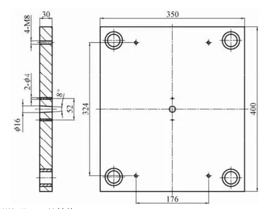
The machining process of the off-cast channel plate is as follows.
(1) scribing: according to the external dimensions of the template, to determine the center of the template to draw the center of the cross, and then from the center to determine the center of the size 52, draw the center of the 2-04 cross, and finally in accordance with the size of the 176×324 country 4-M8 screw holes in the center of the cross.
(2) Milling: Fix the parts on the milling machine, adjust the position, with the molding milling cutter milling φ16 with 8 ° taper taper hole, need to be matched with the taper of the sprue.
(3) Drilling: In the center position of size 176×324, first drill 4 M8 threaded holes and then tap 4 M8 threaded holes in that position.
(4) Drilling: At the center of dimension 52, drill two $4 through holes. If necessary, match two $4 holes in the same position on the fixed mold base plate.
(5) Check the processed dimensions to the drawing requirements.
3) fixed template
Figure 4.97 shows the fixed template parts structure, its material is 718. because the part is a standard mold frame parts, its external dimensions 350x400x220 and 8 guide sleeve already exists, do not need to process. The guide bushings have no effect on the machining of other structural features and do not need to be disassembled. Only need to process the rest of the labeled dimensions can be.
Fixed template machining process is as follows.
(1) scribing: according to the external dimensions of the fixed template, to determine the center of the two sides of the fixed template to draw the center cross, and then the center to determine the size 176×324 to draw the center of the four φ14 through-hole position of the center cross. In the side according to the dimensions marked in the drawing to draw the need to drill the center line of each hole.
(2) Turning: install the parts on a suitable lathe, adjust the center position. Use the turning tool to process according to the curve of the leaning plate (p219.3, and control the taper requirements of 7 °. Turn to SR104.83 about 2mm above the three protruding spheres.
(3) electric discharge machining: first according to the size and shape of the cavity with copper material processing electric discharge process used in the electrode (commonly known as copper male). Then the fixed template parts installed and fixed in the EDM motor to adjust the center position. Then the processed copper male mounted to the EDM discharge motor frame, so that the center of the copper worker and the center of the fixed template parts square. Adjust the relevant process parameters, and finally carry out EDM.
Figure 4.97 Structural drawing of fixed-plate parts
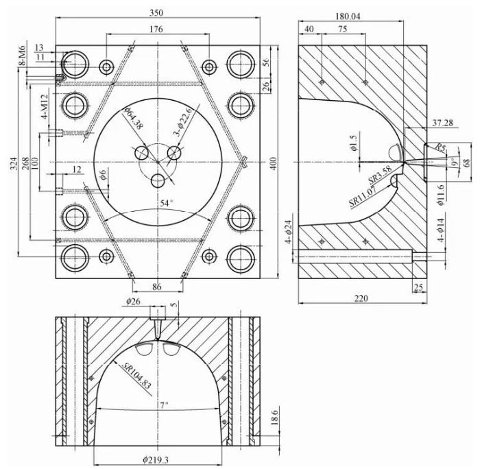
Normally, EDM needs two times of processing to be completed. The first discharge process, the electrode left by the discharge gap is larger, about 0.1 ~ 0.2mm, known as coarse male, discharge processing can be used in the process of larger discharge current processing, can shorten the overall time of discharge processing. The second discharge process, the electrode left by the discharge gap is smaller, for 0.05 ~ 0.07mm, known as the fine male, discharge machining process can be used in smaller discharge current processing, improve the cavity size of the machining accuracy and surface quality.
During the discharge machining, it is necessary to pay attention to the position of the three spherical tabs, which should correspond to the concave position of the dynamic model core, otherwise it will produce interference collision when closing the mold.
On the reverse side, the conical holes of the straight sprue are first milled with a milling cutter, and then the shape and size of the straight sprue are processed with electrode discharge. Then, a φ1.5 sprue hole is drilled with a small-diameter drill.
(4) Milling: according to the size 176×324 draw the center cross line position, milling on the milling machine to process 4 φ14 through holes, and then according to the depth of milling to process 4 o17 step holes. Finally, milling on the reverse side of the 68mm long parting surface sprue.
(5) drilling: in the side, according to the drawings marked drilling two layers of the same position size of the cooling water pipe holes. Drill 8-M6 and 4-M12 threaded holes.
(6) Tapping: Tap out the 8-M6 and 4-M12 threaded holes according to the corresponding depth.
(7) plus plugging: with a brass rod in the drawings marked out the position of the plug, and the table flat countersinking
(8) Polishing: use the cloth to polish the surface of the cavity, so that the roughness of the surface of the cavity to reach Ra0.4um.
(9) check the processed dimensions to the drawing requirements. After installing the water nozzle, check whether there is water leakage on the cooling waterway.
4) dynamic template
Fig. 4.98 shows for the moving template parts structure diagram, its material is 45. because the parts for the standard mold frame parts, its external dimensions 350x400x80, 4 guide pillar holes, 4 closed mold to avoid the fixed mold support guide pillar holes and 6 with the moving mold other plates connected to the fixed threaded holes and so on do not need to be processed. Because the guide pillar has an impact on the processing of other structural features, can be disassembled first, and then assembled back after processing other elements. The moving plate needs to be machined to the remaining dimensions as noted in the “Offset” section.
Fig. 4.98 Structure of moving template parts
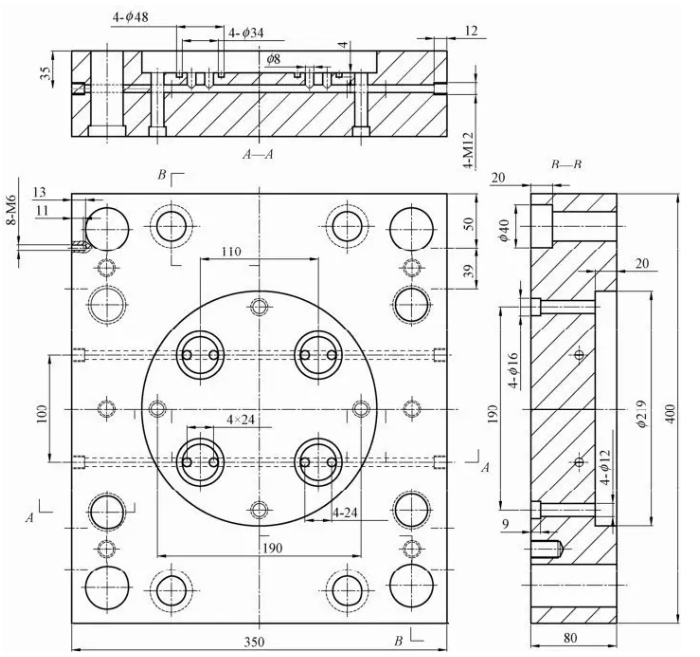
Dynamic template processing process is as follows.
(1) Scribing: According to the external dimensions of the moving template, determine the center of the moving template on the upper and lower two sides of the center of the drawing of the center crosshairs, and then determine the size of the center 190×190, drawing the center crosshairs of the four φ12 through-hole positions. Draw the center line of each hole position to be drilled, such as 8-M6 and 4-M12, etc., on the side according to the dimensions marked in the drawing, paying attention to the direction of the holes.
(2) Turning: install the parts on a suitable lathe, adjust the center position, use a lathe to turn and process φ219, 20 deep circular countersunk holes, which need to be matched with the dynamic model cavity inserts to meet the requirements of their mutual assembly. If there is no suitable lathe, the hole can be processed by boring.
(3) Scribe line: in p219 garden-shaped countersunk holes in the face of the drawing 100×110 of the four center position, the direction in accordance with the parts diagram on the marked position.
(4) milling: the moving template fixed mounted on the milling machine, respectively, according to the drawing of the 100×110 of the four center position milling out the inner diameter of p34, outer diameter (48, depth of 4 of the garden ring groove, in order to assemble the “O | shaped seals with.
(5) milling or drilling: in the center of the size 190×190, first milling or drilling out 4 p12 through holes, and then milling or drilling out 4 φ16, depth of 9 countersunk holes in the position. Note that the direction of the countersunk hole positions is on the opposite side of the φp219 circular countersunk holes.
(6) Milling: Milling and processing of 4 φp40 step holes with depth of 20 in the existing hole position of the reset lever.
(7) drilling waterway holes: in the side of the center distance size 100 and the parting surface height of 35 position drilling 2 (p8) waterway through holes, respectively, in the mouth drilling 4 M12 threaded holes and tapping 4 M12 depth of 12 threaded holes.
(8) Drilling and tapping: process 8-M6 threaded holes according to the position marked on the drawing.
(9) Drilling: On one side of the parting surface, 8 vertical waterway holes of 8 are processed on the surface of φp219 circular countersunk hole according to the position marked on the drawing.
(10) add plug: respectively, with a small copper column in the waterway within the 4×24 position to join the plug, in order to form a cooling circulation channel, refer to the mold assembly Figure 4.85, the
(11) Check the processed dimensions to the drawing requirements.
5) Dynamic mold core insert
Figure 4.99 shows the dynamic model core insert parts structure, its material is S 136.
Figure 4.99 Dynamic Model Core Insert Part Configuration
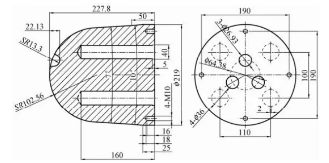
(1) Unloading: Purchase S136 bar with diameter of p225, and the length of unloading is about 235mm.
(2) Heat treatment: annealing of the material to reduce the surface hardness of the material, in order to facilitate the cutting process.
(3) Ironing and turning: milling or turning of one end of the bar to produce a reference plane.
(4) Scribing: Determine the center of the material, and the center as a point of symmetry, to determine the size of 190×190 of the four threaded holes in the center of the position, and then determine the size of 100×110 of the center of the four cooling water pipe holes in the position, pay attention to the orientation of the center of each point.
(5) milling and drilling: milling on the milling machine or drilling on the drilling machine to process 4-φ36, 160 deep cooling water pipe hole and 4-M10 deep 16 threaded bottom hole.
(6) Tapping: Tapping 4-M10 threaded hole, depth 18.
(7) milling: 4 o36 holes as a reference, milling processing out 4 2×40 long groove, depth of 5, in order to install the fixed waterproof piece of use.
(8) turning: roughing, with faster speed and a larger amount of tooling, turning SR102.56, 7 and 10 ° of the taper and φp219 of the outer garden and other dimensions of the shape, leaving 0.5 ~ 1mm of the machining allowance; fine turning, according to the size and shape of the fine-turning to the required dimensions of the numerical value. Pay attention to the arc and taper of the connection transition should be smooth garden.
(9) milling: the center of the garden φ64.38 as a reference, to determine the center of the 3-p26.93 position, milling 3-p26.93 spherical hole and make the hole edge made into a circular transition. Pay attention to the orientation of the hole and the waterway hole, and be consistent with the three projections on the fixed template. Can also use electric spark discharge machining 3-p26.93 of the dowel cao cheng rope border round holes.
(10) Heat treatment: through the quenching and low temperature tempering heat treatment, so that the surface hardness of 60 ~ 65HRC
(11) Polishing: use fine sand cloth to polish the surface of the core, so that the surface roughness of Ra0.4um requirements.
(12) Inspection of the processed dimensions to the drawing requirements.
6) push plate
Figure 4.100 shows the structure of the parts of the push plate, its material is 45. because the part is a standard mold frame on the quarter, its external dimensions of 350x400x30, 4 guide bushings, 4 holes to avoid the fixed mold support guide pillar when the mold is closed, do not need to be processed. Because the guide sleeve has no effect on the processing of other structural features, can not be disassembled. Only need to process the rest of the ornate washbasin area sticky mercaptan caftan note size.
Figure 4.100 Push plate part structure
Push plate processing process is as follows.
(1) scribing: according to the external dimensions of the push plate, to determine the center of the push plate to draw the center cross-hairs.
(2) turning process: the parts are installed on a suitable lathe, adjust the center position. Turning with a turning tool processing φ220, taper 10 ° of the conical hole, the hole needs to move the model cavity inserts with 10 ° taper position to meet the requirements of their mutual assembly.
(3) Milling: the push plate is fixedly installed on the milling machine table, with the center of the holes of the 4 reset rods as the reference, milling and processing of 4-p25 deep 5 step holes; then the push plate is turned over to one side, and the same way milling and processing of 4-φ16 deep 9 step holes.
(4) Check the matching condition of 10°taper hole and dynamic model cavity insert, and check the processed dimensions to the drawing requirements.
7) Pusher fixing plate
Figure 4.101 shows the structure of the parts of the push rod fixed plate, the material is 45, because the parts for the standard mold frame parts, its external dimensions 220x400x25, 4 assembly reset lever step hole, 4 and push rod pad assembly threaded holes, etc. do not need to process. Only the 6 through holes 6-p52, which avoid the support columns, need to be machined.
Fig. 4.101 Structure of actuator fixing plate parts
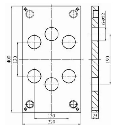
The processing process of the actuator fixed plate is as follows.
(1) Scribing: According to the external dimensions of the actuator fixed plate, to determine the center of the actuator fixed plate to draw the center of the cross, from the center to determine the size of 130×130 to draw the center of the cross of the 4 φ52 through-hole position, and then determine the size of 190 to draw the center of the cross of the 2 φ52 through-hole position.
(2) milling: the push rod fixed plate fixed installation in the milling machine table, respectively, with 6 center head reference, milling processing 6-φ52 through hole. Because of the hole for the support column is to avoid the hole, do not need to consider the relationship between its fit, as long as there is no interference can be.
(3) Check the processed dimensions to the drawing requirements.
8) Push rod pad
Figure 4.102 shows the structure of the parts of the pusher plate, the material is 45. because the parts for the standard mold frame parts, its external dimensions 220x400x30, 4 and the pusher fixed plate assembly screw step holes do not need to be processed. It is only necessary to process 6 through holes 6-qp52 to avoid the support column.
Figure 4.102 Actuator Plate Part Configuration
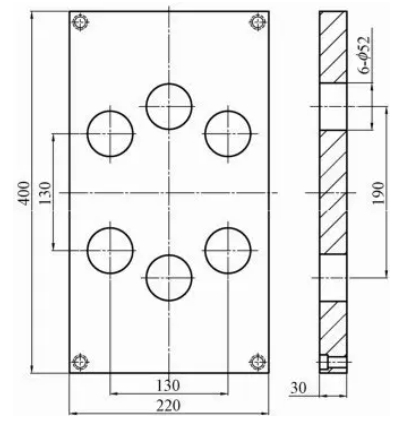
The machining process of the actuator pad plate is exactly the same as that of the actuator fixing plate, and if necessary, the two plates can be clamped together for machining, so that the positional accuracy of its machining is higher.
9) Dynamic mold seat plate
Figure 4.103 shows the moving mold seat plate parts structure, its material is 45. because the parts for the standard mold frame parts, its external dimensions 400x400x35, 6 assembly of moving mold screw step hole, 4 assembly support block screw step hole, etc. do not need to be processed. Only the 6 screw step holes for the assembly support column and the through hole φ50 at the center need to be processed.
Fig. 4.103 Structure of the movable mold base plate parts
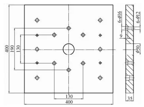
The machining process of the moving mold seat plate is as follows.
(1) Scribing: According to the external dimensions of the movable die plate, determine the center of the movable die plate to draw the center cross, and then determine the size of the center 130×130 to draw the center cross of the 4 φ12 holes, and then according to the size of 190 in the center of the center line to draw the center cross of the remaining 2 φ12 holes.
(2) Milling: Fix the movable mold seat plate on the milling machine table, and mill the through-hole of φp50 in the center of the movable mold seat plate.
(3) Drilling: Based on the dimensions 130×130 and 190, six through holes of φ12 are drilled in the center of the plate.
(4) Milling: Fix and install the movable mold plate on the milling table again, and mill and process 6 φ16 step holes with a depth of 9 in the position of 6 φ12 through holes that have been processed. Note that the direction of the step holes should be in accordance with the direction marked on the drawing.
(5) Check the processed dimensions to the drawing requirements.
10) Gating sleeve
Fig. 4.104 shows the structure of the sprue, whose material is T8A. Since the part is a standardized part, it is only necessary to machine a conical surface with a length of 30 and a taper of 8°.
Figure 4.104 Potting Sleeve Part Configuration
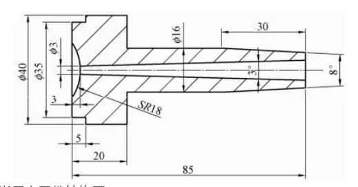
The machining process of sprue sleeve garden taper surface is as follows.
(1)Install and fix the sprue sleeve on the spindle of the lathe, set the tool position, turn and process a taper of 8° and a garden taper of 30mm in length.
(2) Match the turned conical surface with the conical hole on the sprue plate and check the fit until qualified.
- Mold assembly and mold closing
1) Assembly of fixed mold
The fixed mold part mainly includes the fixed mold seat plate, sprue plate, fixed template, gate sleeve, pulling rod, limit screw positioning ring, straight guide sleeve, supporting guide pillar, retaining ring and hexagonal screws and other parts. The assembly process is as follows.
(1) Firstly, install the pulling rod into the fixed mold seat plate, then install the gate set into the fixed mold seat plate, and then install and fix the locating ring and fixed mold seat plate with hexagon socket head screws.
(2)Install the 4 supporting guide pillars on the fixed mold seat plate, then install the sprue plate on the supporting guide pillars and connect them together with limit screws, then assemble the fixed template on the supporting guide pillars, connect them together with limit screws and install the retaining ring at the end of the supporting guide pillars, then fix the ring on the supporting guide pillars with socket head cap screws, and then install the water pipe connector on the fixed template.
2) Dynamic mold assembly
Dynamic mold part mainly includes dynamic mold plate, dynamic template, push plate, push rod fixed plate, push rod plate, dynamic model core inserts, reset lever, compression spring, support column, support block, sealing, waterproof piece and hexagon socket screws and other parts.
The assembly process is as follows.
(1) Firstly, install the waterproof piece into the moving model cavity insert, then install the 4 seals into the circular groove in the moving template, and then assemble the moving model cavity insert and the moving template together with the socket head cap screws.
(2) Assemble the reset lever, push rod fixing plate and push rod pad plate together with hexagonal screws.
(3)Assemble the support block with the movable mold seat plate with 4 socket head cap screws, then assemble the 6 support columns with the movable mold seat plate with socket head cap screws, load the assembled reset lever, push rod fixing plate and push rod pad plate parts from the support columns, and then assemble the movable mold plate equipped with movable mold core inserts with the movable mold seat plate and other parts with 6 socket head cap screws, and put the push plate from the movable mold core inserts Install the push plate from the moving mold core insert and pay attention to the fit of the taper surface, and finally use 4 hexagonal screws to fix the push plate to the reset lever. - 3) Mold clamping
- Fixed mold and moving part of the mold through the guide pillar, the guide sleeve to close the mold, pay attention to the guide pillar, the guide sleeve should be easy to work with. With red Dan coated on the parting surface of the contact parts, to see whether the fit gap meets the requirements. If the gap is too large, it should be corrected by grinding.
- Close the mold and then assemble the opening hook. Finally, pass in the cooling circulating water, check to see if there is any water leakage. Finally, the mold will be assembled to the injection machine for mold testing.

